
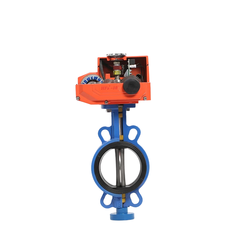
Leakage class is one of the few valve specifications that a buyer can verify on a test bench rather than accept on a datasheet. Yet it is also one of the most frequently misread, because the number quoted — Class A, Class VI, zero leakage — describes a test result under specific conditions, not a property the valve carries with it into every installation. This article explains how seat design produces (or fails to produce) tight shutoff, what the common leakage standards actually measure, and which installation details decide whether a valve that passed its factory test still seals after six months in service.
What Leakage Class Actually Measures
A leakage class is the result of a defined test: a valve is closed, a specified test medium is applied at a specified pressure, and the permitted leakage is expressed either as a rate of bubbles, a volume per unit time, or a fraction of rated capacity. Change the medium, the pressure direction, or the temperature, and the same valve can fall into a different class.
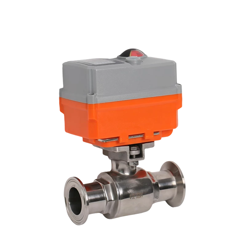
Chinese-manufactured industrial valves commonly cite GB/T 4213-92, under which Class A denotes the tightest category available. Products in this range, such as the sanitary electric ball valve (DN15–57, PN1.0–1.6 MPa) and the electric miniature 304 ball valve (DN8–25), both specify GB/T 4213-92 Class A. What that means in practice is that the seat and ball have been lapped to a fit that does not permit measurable through-leakage at the rated pressure under the test conditions — it does not mean the valve will remain bubble-tight after the medium has deposited solids on the seat.
Three variables move a valve away from its tested class:
- Differential direction. A soft-seated ball valve is typically tested and rated for unidirectional sealing. Installed so that pressure bears on the wrong side of the seat, it can leak at a rate several classes worse than its rating.
- Temperature drift. The seat material sets the usable temperature ceiling, and approaching that ceiling softens the seat and reduces its contact stress.
- Media with solids. A Class A rating is established with a clean test medium. A process stream carrying particles will score or embed material in the seat, and the leakage class degrades with every cycle.
Soft Seating versus Metal Seating
Seat construction is the primary decision, and it is a trade rather than a ranking. Soft seats seal by deformation — the elastomer or polymer conforms to the ball or disc surface, filling microscopic irregularities and achieving tight shutoff with modest actuation torque. Metal seats seal by precise machined contact, which tolerates high temperature and abrasive media but cannot conform, so the achievable tightness is inherently lower.
| Consideration | Soft seating | Metal seating |
|---|---|---|
| Sealing mechanism | Elastic deformation of the seat | Machined metal-to-metal contact |
| Achievable tightness | Tight shutoff, Class A achievable | Lower class; leakage path remains |
| Temperature ceiling | Set by the polymer (see table below) | Limited only by the metals used |
| Abrasive media | Seat damage accumulates | Tolerated far better |
| Actuation torque | Lower | Higher |
| Typical fit | Water, air, gas, food and pharma service | Steam, high temperature, slurries |
The seat materials offered across this product range illustrate how the temperature ceiling is set by chemistry rather than by the valve body:
| Seat / seal material | Characteristic | Where it is specified |
|---|---|---|
| PTFE | Broad chemical resistance, moderate temperature | Threaded ball valve (−10~120°C), sanitary ball valve (−20~180°C), miniature ball valve (−20~80°C) |
| NBR | Standard elastomer for water service | Latching butterfly valve (standard seat) |
| EPDM | Improved water, steam and weather resistance | Butterfly valves, PVC three-way valve |
| PPL | High-temperature alternative to PTFE | Miniature ball valve, wafer butterfly valve (high-temperature option) |
| PEEK | High temperature with high mechanical strength | Pneumatic flanged ball valve |
| FKM | Chemical and heat resistance | Electric PVC three-way ball valve |
| Metal seal | No polymer in the sealing path | Miniature ball valve, wafer butterfly valve (high-temperature option) |
Note that several products list multiple seat options rather than one, and that the temperature range quoted in the specification belongs to the option actually fitted. A wafer butterfly valve rated ≤80°C with a PTFE seat is not an ≤80°C valve if the customer fits a metal seat instead — the ceiling rises, and the leakage class changes with it.
How Seat Design Produces Zero Leakage
The tightness that earns a Class A rating comes from three design details that work together, and understanding them makes it easier to judge a quotation.
- Seat contact stress. The seat must be compressed enough that the polymer flows into the surface finish of the ball or disc. Too little stress leaves a micro-path; too much deforms the seat permanently and creates a leak after a few thousand cycles. This is why a valve rated for a lower pressure is not simply a derated version of a higher-pressure one — the seat geometry differs.
- Seat retention. In a ball valve the seat is held against the ball by a combination of upstream pressure and mechanical pre-load. The two must be compatible: a seat designed to rely on line pressure will not seal at low differential, and a seat designed to rely purely on pre-load will lose contact as the polymer relaxes.
- Ball or disc finish. A lapped spherical surface with consistent roundness lets the seat conform uniformly. Localised high spots produce localised leakage regardless of how well the seat material performs.
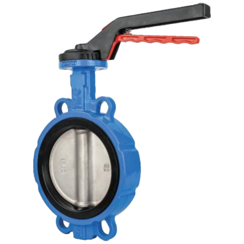
The latching butterfly valve (DN50–500, PN1.0–1.6 MPa, wafer connection, 304/316 stainless body) illustrates a different approach: instead of a sphere, the disc closes against an elastomeric liner that surrounds the full circumference, so the seal is a continuous ring rather than a spherical contact. This soft-sealed structure is what allows a wafer-pattern valve to hold on media including potable water, sewage, seawater and weak acid or alkali solutions across −10~120°C.
Installation Factors That Decide Whether the Rating Holds
A valve that passed its factory leakage test can still fail in service for reasons that have nothing to do with the seat. The most common, in order of how often they appear in field diagnosis:
- Pressure applied against the designed sealing direction. Confirm the intended flow direction against the arrow or documentation before installation, especially on soft-seated ball valves.
- Weld debris or pipe scale trapped on the seat. Any particle that lodges between seat and ball at the first closure may be pressed into the polymer permanently.
- Misalignment imposing side load on the stem. Flange faces that are not parallel force the stem sideways, distorting seat contact and accelerating wear.
- Operating at the temperature boundary. Running a PTFE-seated valve continuously at its ceiling accelerates creep and loosens the seal.
- Actuator torque mismatch. An actuator sized for a lubricated ball valve may be unable to develop the seating torque required by a dry or high-temperature seat, leaving the valve not fully closed.
The last point connects the sealing discussion to the actuation discussion, because on an automated valve the two cannot be specified independently. A seat that needs higher closing torque requires a larger actuator, and an actuator that closes too hard on a soft seat will crush it over time. Where both requirements must hold — tight shutoff and long cycle life — the correct approach is to specify the seat material, the required leakage class, and the available actuation torque together, in one document, rather than as three separate line items.
Verifying a Delivered Valve
Because leakage class is a test result, it can be confirmed. Four checks establish whether a delivered valve will perform as specified, and all can be performed without special equipment beyond a pressure source and a means of measuring leakage.
- Seat leak test in the intended flow direction. Close the valve, apply the rated differential from the designated upstream side, and observe leakage over a defined period. Record the result against the class claimed.
- Back-seat test if the rating claims bidirectional sealing. Repeat with the pressure reversed. A valve that seals one way and not the other is functioning as designed, not as described.
- Cycle test before acceptance in critical service. Operate the valve through a significant number of cycles with the process medium, then repeat the seat test. A valve whose leakage class degrades quickly will do the same in production.
- Torque verification at operating temperature. Measure the breakaway and seating torque hot if the process runs near the seat ceiling. Cold torque measurements understate the requirement.
For installations where the medium is clean and the temperature is well inside the seat rating, the factory test result is usually reproduced without difficulty. Where either condition is marginal, the specification should state the test medium, the pressure, the direction and the temperature, because those four parameters define what the claimed class actually means for that application.